|
 IBETON |
| login | course | team & projet | help |
|
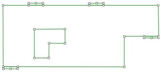
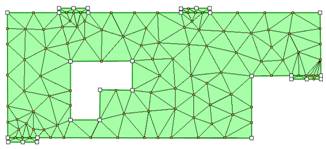
Input of the steel loading platesIn reality, point support and point loads do not exist: structures are supported on supports that have nonzero dimensions, and loads are also introduced over nonzero surfaces. This is why Figure 1 shows black steel plates at the locations of the supports and load introduction. It is not strictly necessary to model these plates when performing a linear elastic analysis, in which quasi-infinite stresses are acceptable, if not realistic, but, as our goal is to perform realistic calculations of non-linear reinforced concrete elements, it is useful to introduce these plates. Otherwise, local failure modes at the points of supports or load introduction may occur. To do that, introduce the plates (first deactivate the FE mesh, and then activate the background image). A new area can be created very simply by reusing an existing node (on the lower left corner of the figure to start, then go around the plate, not forgetting to add a node at the point where we will later introduce the support. Notice that when you move the mouse close to an existing element (node, but also area edge), this element gets highlighted, indicating that the next node will be either the highlighted node, or placed precisely on the highlighted segment. If you want to START a new area on an existing area edge, you will notice that simply clicking is not sufficient. Indeed, in this case, the area gets selected, for further use. If you then want to add a node on that area edge, simply press the Shift key on your keyboard while pressing the mouse button. After inputting all areas, here is how your structure should look like : Fig. 7a with only the areas and Fig. 7b with the corresponding mesh.
But wait! we need to tell the program that the plates are made of steel and not of concrete as the rest of the structure. By default, iMesh will consider that all areas that you input are made of concrete, and also give it a default thickness. You can see these default values by carefully clicking on an existing area (it should change color to indicate that you selected it) and then pressing the
Figure 8: Input of material and geometric propertie Let’s now select the four plates. To do that, select the first plate (your choice). It should become highlighted and the larger are that was formerly selected should look normal now. Now, press and hold the Ctrl key on your keyboard and select the other two plates. Then press the
Figure 9: Selection of steel as the material for the steel plates |
||||||||||||||||||


